Home| Capabilities & Services | Materials | Applications | Customer Service Hotline

Home|
Capabilities & Services |
Materials |
Applications |
Customer Service Hotline
8610 CENTRAL AVE, STANTON, CA 90680
TEL. 714-484-7500 * FAX 714-484-7600 * ![]() E-MAIL newportglass.sales@gmail.com
E-MAIL newportglass.sales@gmail.com
![]()
Whether you have worked on telescope glass, or this is your first attempt at precision glass work, approach the task with careful attention.
The finishing of a fine doublet lens is nothing more complicated than performing a large number of small but important steps thoughtfully
and correctly. Long before you make the last few steps and hold the prize in your hands you will have acquired the skill and understanding
to make the work easy, for work it is.
Upon unpacking your refractor kit you will have observed that the two lens elements have radii molded onto them, and that each blank has
been precisely edge ground. You will have noted also molded plate glass tools have been furnished containing the curves of opposite sign
for grinding the lenses. These preparations simplify your task. The all important matter of keeping the lens curves centered, that is maintaining
uniform edge thickness to tolerance, is made easy with ground edges. A simple test, to be described later, enables you to keep track of
centering with surprising accuracy. The instructions that follow are based upon the assumption that you may have little or no experience in
glass working. The procedures will suffice for inexperienced workers to make a satisfactory achromatic doublet lens of the cemented kind.
Experienced workers will of course, follow their well practiced techniques.
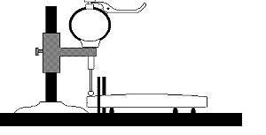
The measuring tool shown in Figure 1 is essential in the making of refractor lenses, indeed it is quite hopeless to control wedge and center
thickness without it.

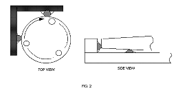
This fixture can be simplified without detriment. For example, The base may be made of wood, and 3/8 inch ball bearings cemented into lightly drilled dimples to replace the three pegs shown above. The two tall pegs which confirm the lens laterally, can with advantage,
be replaced by a 90 degree V with 1/4 inch ball bearings cemented to its faces as sketched below.

The dial indicator should be positioned over one of the 3 3/8 inch balls to prevent tilt of the lens. The balls may be covered with teflon
to prevent scoring. An extension arm must be provided to place the dial plunger over the center of the lens for measuring center thickness.
Two other tools are essential in making a cemented doublet lens whose rear radius is flat: A flat test plate at least 1/2 the diameter of the doublet, and an aluminized flat-full size or larger-to test the cemented lens in its cell. The test called OautocollimationO can be used to fine-tune color and spherical aberration in any doublet.
If you do not have a power driver spindle to aid in grinding the glasses you must secure the lens on top of a weighted barrel, or pedestal,
or if none of these is available, the corner of a bench will serve so long as you can walk freely three quarters of a circle around the corner.
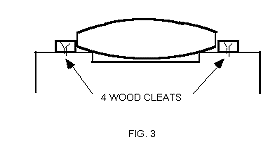
It is necessary to fasten the lens to the grinding platform. Let the convex blank be worked first. It can be taped around its edge to a block
of same diameter using duct tape or masking tape, or it can be placed in a wood holder as in figure 3.

To begin grinding operations a small pan partly filled with #220 or #240 carborundum or Aloxite mixed with water is placed nearby with a one inch paint brush in it to apply the mixture to the surfaces. Apply some to the lens and the grinding tool (the latter being the glass tool or the concave of the flint element). The two are placed together, the upper glass held at the edge by fingers and thumb of both hands. Moderate pressure applied, the tool is slid forth and back over the lens. The excursion, should be no longer than one third the diameter of the lens.
While rubbing one glass over the other shuffle slowly around the pedestal or bench corner, rotating the tool slowly, and from time to time turn
the bottom element 15 or 20 degrees.
As soon as the sound of grinding that is the noise of abrasive grains rolling between the surfaces become faint, slide the tool and add abrasive. Keep this up for 15 or 20 minutes. Prolonged grinding like this causes the upper glass, if concave, to become more concave, the lower glass more convex. If the glasses are reversed-concave on the bottom, both elements will become longer radii. Thus the radius can be controlled.
There are several ways to measure radius; let us consider two of them, the spherometer and the metal template. If a spherometer is available its
use is recommended with a warning. The spherometer reading is a small decimal fraction from which the radius, a comparatively large whole number, is calculated. Keep in mind that a small error of spherometer reading contributes a large error in the calculated radius. Professional lens makers use spherometers, but they make a fetish of technique so as to insure constant reproducible readings.
The other measuring tool, the metal template, is a precisely machined brass plate containing the prescribed radius. The curved edge is placed upon the lens, the fit is sighted against
a bright background, the slightest departure from true fit is easily seen. This method is quick, easy to use, and surprisingly accurate. A telephone call to the nearest spectacle lens lab will get you in touch with its source of templates.
After a spell of #220 grinding check the radius. Also check the lens center thickness, and also the centering, commonly called OwedgeO. Wedge should be maintained at less than 0.001 during #220 grind, with #400 grind which follows #220, the wedge must be kept below 0.0004 inch. You will be happiest in the end if the wedge were at or below 0.0002 inch when 9 micron grind is completed. To measure wedge place the clean dry lens on the fixture shown in figure 1, with the dial plunger resting just inside the rim. When the lens is rotated while gently pressed into the 90 V, the dial will rise and fall if wedge is present. More pressure applied to the high point when grinding will soon reduce the wedge. In general practice a lens is brought to within 0.010 inch per side above the specified thickness with #220 grit. With #440 grit 0.005 is removed. With 9-10 micron grit 0.003 to .004 is removed per side. Glass removed by polishing is so small that no attempt should be made to measure it.
Before moving to #400 grit it will be necessary to bevel all sharp edges of the lenses. (It has been assumed that both sides of the bi-convex lens were ground with #220 grit, removing one half the surplus glass from each side). If you are making the cemented doublet and are using the flint lens to grind the mating curve, watch the center thickness of the flint lens so as to leave sufficient material to grind the flat side. To bevel the edges, abrade the sharp corners with a #220 carborundum stone held at a 45 degree angle with copious quantities of water upon the lens and the stone. The bevels should be a sixteenth of an inch face width. Do not use this procedure on the acute edge of the concave lens, instead grind it first on a flat surface with #400 until a flat border one sixteenth of an inch wide is produced. The outer sharp edge of this border may then be OstonedO at 45 degrees. The lens is now protected from chipping as the work proceeds.
When satisfied with the radius R1 & R2 & R3 at the end of #220 grinding, it is time now to grind R4, the flat surface of the flint lens. The flat surface of the R1 grinding tool is used to grind the flint R4. This contains an unexpected benefit-this plano-concave tool is polished on the concave and flat surfaces, the concave surface can be measured by knife-edge or Ronchi test to verify its agreement with the desired value for R1, and also to verify its spherical figure. More of that a bit later when it is used as a test plate for R1.
All #220 abrasive is removed from the work area and a thorough cleanup is made before starting #400 grind. With this grain size ground off .005 inch from each radius, maintaining wedge of 0.0005 inch or less, and keeping the radii to gauge or spherometer. To gauge the flat surface a true straight edge a 12 inch machinists rule will suffice. Clean things up again and fine grind the surfaces with 9-10 micron grit.
Before polishing these surfaces you should make two discs of 3/4 inch plywood or pressed wood the diameter of the lens you are making. One of these should be filed or sanded on one side to a convex curve roughly equal to R1 or R2. Shellac these discs to make them waterproof. They are forms on which pitch is poured and shaped to polish the lenses.
Before dealing with the polishing process it is necessary to take up the matter of a monochromatic light source for interference fringe testing of the lens surface. An ideal source of such light is a readily available 15 inch (longer are available) fluorescent tube made by GE, #F15T8-BL. This lamp suspended above the workbench with a diffusing screen below it gives adequate illumination of the interference fringes. The test glass and lens surface, quite clean and lint free, are placed together a little off center. A circular pattern of fringes is seen, many fringes indicate large difference in radius, few fringes little difference. A three fringe match is adequate.
To determine whether the surface being tested is of longer or shorter radius, apply gentle finger pressure to the center of the test glass. If the circular pattern shrinks, the fringes closing upon the center, the tested radius, if convex, is longer than the test glass. If the shrinking pattern is seen at a concave tested surface the concave radius is shorter than the test glass. Conversely, if the fringe pattern expands, spreading out from the center under pressure, the tested radius if convex, will be shorter than the test glass. A tested concave radius if longer than the test glass will show expanding fringes. A handy way of remembering this is to think that pressure causes the fringes to move OdownhillO. With this insight you can adjust any radius to as perfect as it need be. It is up to you to finish all surfaces to the measured test glasses within at most three fringes perfectly circular, and showing no change at the edge of the lens. Remember also that the test glass always must be placed on the lens somewhat off center, for if this is not done it is impossible to judge perfect circularity of the fringes.
Now to polishing. Since much literature is available on polishing pitch this leaflet will not deal with the subject. You are referred to Amateur Telescope Making, books 1,2 and 3, S & T Gleaning, De Vany Texereau, et al. We left off above with two shellacked wood discs, one convex, the other concave. With gummed paper, duct or masking tape wrap the edges of these discs to provide a circular dam three eighths of an inch high above the surface. Pour melted pitch level full into the concave disc and allow the pitch to cool somewhat. When cool enough to be pliable, not fluid, press into it the convex R2 that has been smeared with a water slurry of Cerium Oxide or Barnesite. As the lens sinks into the pitch, material bulges out at the edge.
Push it back against the lens while moving the lens around over the pitch until a complete fit is obtained. Remove the lens at this point and chill the pitch by immersion in cool water, then strip off the dam. Repeat this operation with the second wood tool, stripping off the tape dam before shaping the soft pitch with the concave lens. Do not press the lens directly onto the pitch, for you will entrap air and have a flat spot in the center. Instead, press the lens, off center, around the edge to depress the pitch there so that when the lens is slid around over the top of the pitch, no air will be entrapped and there will be a better chance to obtain a uniform fit all over. Pitch will bulge out and overhang the edge but this can be trimmed off after the shaping is finished. If, also, your effort turns out poorly you can soften the pitch in hot water and smooth it out.
Before these shaped polishers can be used they must be faceted by cutting channels with a razor blade, or embossed by pressing them with one quarter inch fish netting that has been dipped in water containing a detergent to facilitate removal from the pitch. Embossing is done by draping the wet netting over the lens and pressing the hot water softened pitch onto the netting.
The first polishing task is with the polisher shaped by R3. As in the grindings this polisher is fastened to the pedestal, the concave lens rubbed over it until there is enough OshineO to perform a knife-edge and Ronchi test. With the knife edge tester or Ronchi at the center of curvature measure the distance between the knife edge or grating and the lens.
This is of course, the radius and if it not within one twentieth of one percent it must be reground with R2, polished & tested until it is ok. When found to be correct, polish the surface completely verifying its radius and smooth sphericity, because this surface will be the test glass for R2. Set it aside for the present after painting it with Krylon or Rustoleum. The plate glass tool that ground R1 is now to be polished. The concave side is pressed on the warmed pitch polisher that finished R3. The operations done on R3 are repeated except that the surface need not be completely polished. When the radius measures within one twentieth of one percent, a good OshineO and a perfectly spherical figure is all that is needed.
The next step is to polish the flat surfaces of the R1 test glass and R4. Remove pitch from the convex polisher, turn the wood disc over and pour a three eighths inch of pitch on the flat side. Use this to polish the flat of R1 test glass until it is clear enough to see through, then begin polishing R4. If a flat test plate is on hand this surface may be polished completely, monitored for figure as polishing proceeds. A three or four fringe fit will be adequate. If no flat test glass is available, polish R4 anyway. Whatever may need correcting may be done later.
R1 and R2 are next to be polished, The polisher already made can be warmed and pressed to whichever radius you wish to polish first. As polishing proceeds, use the test glass as needed to bring about a 3 fringe or better match for both sides of the biconvex lens. When these two radii are finished, and you were able to control R4 with a flat plate, the lens is now finished and needs only to be cemented together and it is ready for use.
Cementing an achromat used to be a difficult task even dreaded by professionals if the diameter exceeded four inches. Certain modern developments have taken away the difficulties so that large diameter lenses can be joined with no ill effects. They are not cemented actually they are oiled and taped. Clean the lenses in detergent laced water rubbing the glass with a soft cloth, rinse with tap water and dry with cotton cloth. With a black felt marking pen blacken the ground rims of both lenses.
Place them, cemented side up, on lintless paper on a level surface. Lightly dampen a wad of clean absorbent cotton with rubbing alcohol, and with moderate pressure and circular strokes scrub the entire surface. Before the alcohol dries apply a dry cotton pad to the surface, continuing to rub over the entire surface until it is dry. When both surfaces are cleaned in this manner and all cotton filaments left have been blown off with a syringe, add half dozen or so drops of clean salad oil to the center of the concave lens, taking care to see that all the drops of oil have formed a single puddle. Now lower the mating surface of the crown lens onto this puddle without entrapping air and let the lens settle into the oil unaided. The oil will spread out in a thin uniform film. Oil that seeps out at the edge is wiped off with kleenex. The pair is now taped together with thin (0.003 -0.0035) plastic tape; two thicknesses is best around the rim, the end of the second course should not overlap the underlaying beginning of the tape.
The lens is now ready to place in the cell and be tested on the moon and stars.
Author: Max Bray, Graphics: Newport Glass Works, Ltd.